Manufacturing Equipment Redesign · 2026
Copper Plate Extension for Electrocoating Barrel
Improving maintenance accessibility, reducing downtime, and increasing electrical reliability through practical mechanical redesign.
- Duration
- 4 weeks
- Role
- Design Engineer
Overview
Project Overview
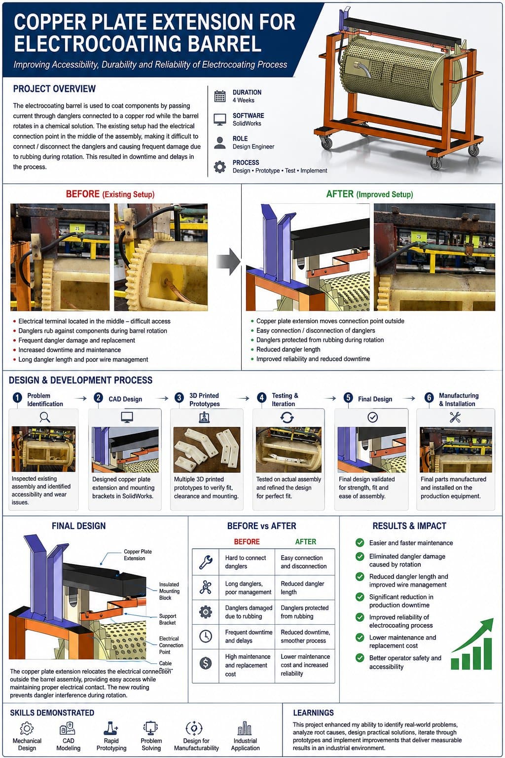
The electrocoating barrel coats components by passing current through danglers connected to a copper rod while the barrel rotates in a chemical solution. In the existing setup, the electrical connection point sat in the middle of the rotating assembly, making it difficult for technicians to connect or disconnect danglers and causing frequent damage as they rubbed against components during rotation. That damage translated directly into downtime and delays in the coating process.
The Problem
Engineering Challenge
The original design created a chain of related problems, all traced back to one decision: putting the electrical terminal in the middle of a rotating assembly.
- Electrical terminal located in the middle of the assembly — difficult to access
- Danglers rubbed against components during barrel rotation
- Frequent dangler damage and replacement
- Long dangler length and poor wire management
- Increased downtime and maintenance effort
Root Cause
Problem Investigation
I inspected the existing assembly on the production floor and traced the accessibility and wear issues to the interior-mounted connection point. Root causes centered on rotation clearance, cable routing, and a design that had never accounted for maintenance access as a requirement.
What It Had to Do
Design Requirements
How It Was Built
Design & Development Process
Problem Identification
Inspected the existing assembly and identified accessibility and wear issues tied to the interior connection point.
CAD Design
Designed the copper plate extension and mounting brackets in SolidWorks to relocate the connection point outside the barrel assembly.
3D Printed Prototypes
Produced multiple 3D printed prototypes of the mounting brackets to verify fit, clearance, and mounting before committing to metal parts.
Testing & Iteration
Tested the design on the actual production assembly and refined it for a precise fit.
Final Design
Validated the final design for strength, fit, and ease of assembly.
Manufacturing & Installation
Final parts were manufactured and installed on the production equipment.
CAD Development
Design in SolidWorks
Before vs After
What Changed
| Aspect | Before | After |
|---|---|---|
| Dangler connection | Hard to connect / disconnect | Easy connection and disconnection |
| Wire management | Long danglers, poor management | Reduced dangler length |
| Wear | Danglers damaged by rubbing | Danglers protected from rotation contact |
| Downtime | Frequent downtime and delays | Reduced downtime, smoother process |
| Maintenance & replacement cost | High | Lower, with increased reliability |
Final Implementation
Result
Impact
Results
Reflection
Lessons Learned
Designing for maintainability has to be a stated requirement, not an afterthought — the original design failed because accessibility was never a constraint.
Clear communication with maintenance technicians on the floor surfaced the real failure modes faster than reviewing drawings alone.
3D printed prototypes made it possible to validate fit and clearance cheaply before cutting any production material.
Manufacturing constraints (existing mounting points, minimal downtime for installation) shaped the design as much as the electrical requirements did.
Engineering validation on the actual equipment — not just in CAD — was what gave confidence to move to production.
Technology Used
Skills Applied
Keep Exploring