Maintenance & Reliability Engineering · 2026
Hoist Castor Redesign
Eliminating welded maintenance operations through improved mechanical design.
- Duration
- Design phase
- Role
- Design Engineer
Overview
Project Overview
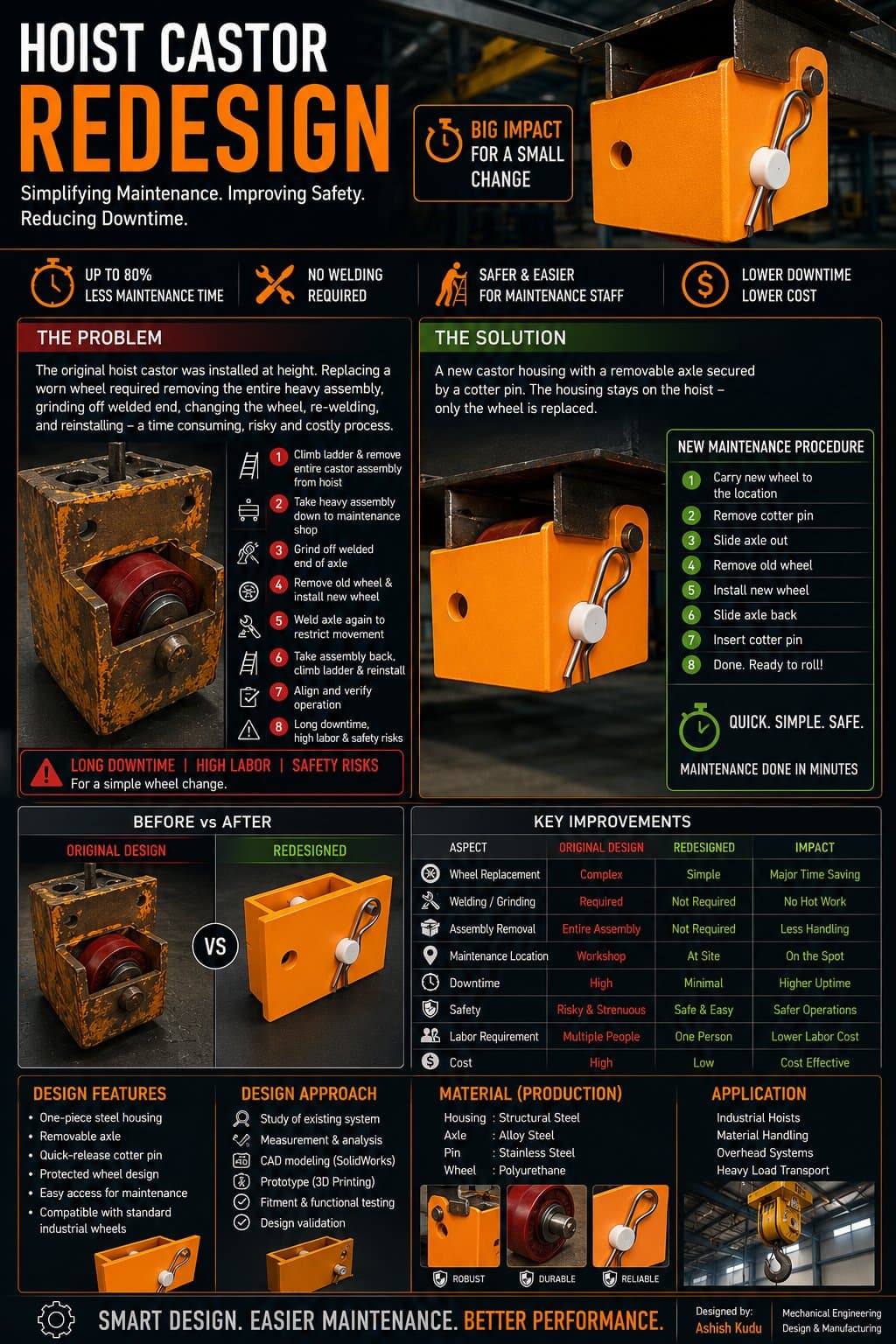
Hoist castor wheels mounted at height required a multi-step procedure to service: climb a ladder, remove the entire heavy castor assembly, grind off the welded end, replace the wheel, re-weld the axle, and reinstall. That process was slow, physically demanding, and carried real safety risk for maintenance staff for what is fundamentally a simple wheel change.
The Problem
Engineering Challenge
The original hoist castor was installed at height, and every wheel replacement carried the full weight of a welded repair job.
- Required climbing a ladder to access the castor at height
- Removal of the entire heavy castor assembly from the hoist
- Grinding off the welded end of the axle
- Wheel replacement followed by re-welding to restrict movement
- Reinstallation, alignment, and verification back at height
- Long downtime, high labor requirement, and safety risk for a simple wheel change
What It Had to Do
Design Requirements
How It Was Built
Design & Development Process
Problem
Studied the existing system and measured the time and steps required for a routine wheel change.
Inspection
Measured and analyzed the installed castor housing and mounting interface.
Concept
Developed a removable-axle concept secured by a cotter pin, keeping the housing fixed to the hoist.
CAD
Modeled the one-piece steel housing, alloy steel axle, stainless pin, and polyurethane wheel in SolidWorks.
Prototype
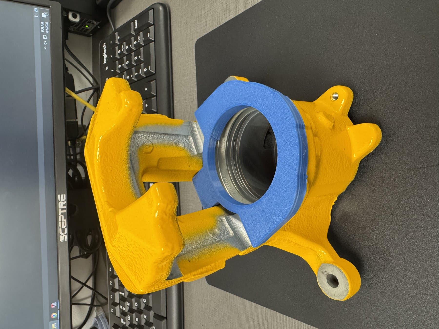
3D printed a prototype housing to validate fitment and the cotter pin retention mechanism.
Final Design
Verified fitment and function, confirming compatibility with standard industrial wheels.
CAD Development
Design in SolidWorks
Prototype
Physical Validation
Before vs After
What Changed
| Aspect | Before | After |
|---|---|---|
| Wheel replacement | Complex | Simple — major time saving |
| Welding / grinding | Required | Not required — no hot work |
| Assembly removal | Entire assembly removed | Not required — less handling |
| Maintenance location | Workshop | On site — higher uptime |
| Downtime | High | Minimal |
| Safety | Risky and strenuous | Safe and easy |
| Labor requirement | Multiple people | One person |
| Cost | High | Low — cost effective |
Final Implementation
Result
Impact
Results
Reflection
Lessons Learned
A small mechanical change — removing the need for welding — produced an outsized reduction in downtime and labor.
Designing for maintainability meant treating the wheel as a replaceable wear item from the start, not something bonded permanently into the assembly.
3D printed prototypes were essential for validating fitment before committing to steel and alloy components.
Keeping the housing compatible with standard industrial wheels made the redesign practical to adopt without new sourcing.
Technology Used
Skills Applied
Keep Exploring